Innovating Cathodic Arc Deposition: High-Performance Bias
Posted February 11, 2014 by Uwe Krause
The “field” we work in (That’s why we are called “field" applications engineers.) involves an endless variety of technology and customers. Sputtering comprises a large part of this field, but cathodic arc coating is another a significant application we work with. And, yes, this application, too, is characterized by an endless number of processes and combinations of technologies and tool designs.
To give an example, in the European Union, road transport is the second biggest source of greenhouse gas emissions, right after power generation. It contributes about one-fifth of the EU's total emissions of carbon dioxide (CO2). Under EU regulations, average CO2 emissions from cars should not exceed 130 g CO2 per kilometer by 2015, and should drop further to 95 g/km by 2020. So, car manufacturers need to find ways to decrease friction in order to save gas, as gas conservation is an effective way to reduce CO2 emissions. This could be realized several ways, one of which is using hard-coating tools to create layer stacks for increasing wear resistance and decreasing friction.
For this application, there are several ways to create plasma inside the tool, but the majority of them use a bias power supply.
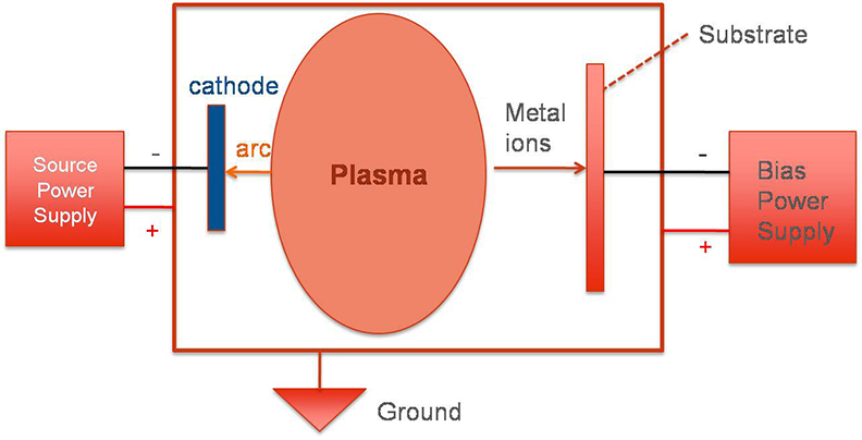
As long as the substrates are conductive, one can run the bias power supplies as DC or pulsed DC. However, non-conductive substrates require an RF supply in order to create a sufficient bias voltage. The purpose of the DC and pulsed DC bias power supply is to apply a direct voltage against ground, and depending on the process windows, to guide the ions to the substrate.
For tools performing arc evaporation, a bias is virtually mandatory. The process window of these bias power supplies is quite large. Processes run with low bias voltages, even below 50 V, on one edge of the process window, and also high voltages, up to 1000 V, on the other side. Of course, the state-of-the art power supply needs to be tapless (no tap to switch for customers at the output), with a wide impedance range.
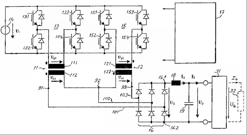
US Patent 6,567,278
So, you have to find a way to deliver a stable voltage output between, let’s say, 20 V and 1000 V. This unit must be robust and highly efficient. Last but not least, all of these parameters must be available at an acceptable price.
The figure above shows the implementation of a wide impedance range in one unit without taps in the output transformer. In fact, the unit combines the parallel (for high current) and serial (for high voltage) operation of two inverters. Built for bias operation and with many years in the field, this concept is proven through real-world performance.

Uwe Krause
Related Posts
Blog

.jpg?resizemode=force&maxsidesize=884)