Dynamic Reverse Pulsing – What About the Anode?
Posted December 04, 2023 by Gayatri Rane
A previous AE blog, Dynamic Reverse Pulsing – What About Duty Cycle?, discussed reactive sputter deposition of insulating thin films in large-area coaters, describing the benefits of using the Dynamic Reverse Pulse (DRP) power-delivery mode over the bipolar (BP) mode of dual magnetron sputtering. In DRP mode , dual targets are bipolar pulsed against an explicit anode and the duty cycle can be varied so that the polarity is positive on the target for a shorter time during pulsing. This allows clearing of charge build-up on the targets. In our studies, DRP mode showed increased deposition rate and reduced substrate temperature when compared to similar depositions with the BP mode.
Understanding the Effect of the Anode
The main difference between DRP mode and BP mode is the presence of an explicit anode in the former. To understand the effect of the anode further, we designed new tests to study the effect of increased anode area and their placement on the deposition process and film properties.
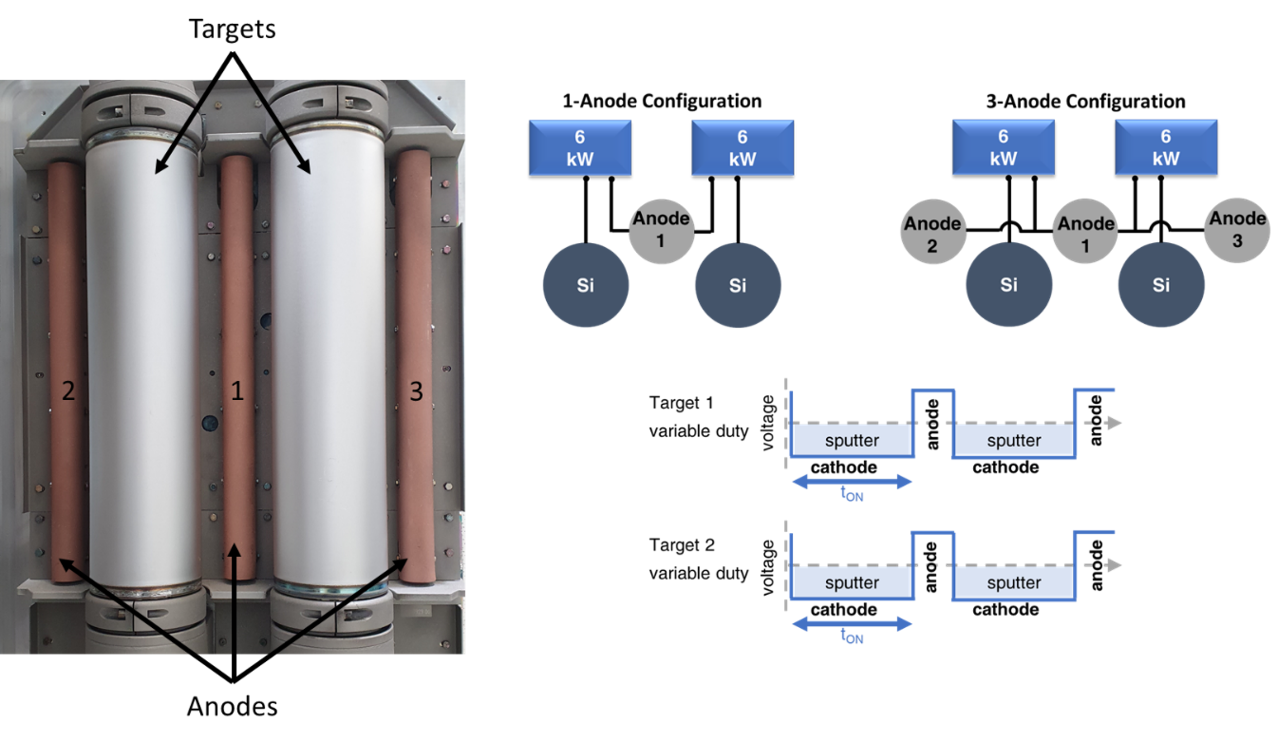
Figure 1 shows 2 anode configurations that were compared in an industrial drum coater. In the first case, the two targets were pulsed against the single anode bar present between the two targets (1-anode configuration). In the second case, the two targets were pulsed against three anode bars — one present between the two targets and the other two on either side of the targets (3-anode configuration).
.png "1-(1).png")
Figure 1: Placement of anodes and target for DRP testing. In 1-anode configuration, only anode number 1 was used. In 3-anode configuration, anodes number 1, 2 and 3 were connected together. The equivalent circuits are shown on the right. Tw Ascent AP DMS power supplies were used for these tests, each powered to 6 kW.
The Si targets were sputtered at a total power of 12 kW in an Ar/N2 gas mixture to deposit silicon nitride thin films on glass. The Ar flow was fixed to 100 sccm. Table 1 provides the tested DRP settings (duty cycles and pulsing frequencies).
The discharge voltage variation as a function of N2 gas flow is shown in Figure 2 for the 1-anode and 3-anode configurations. For each DRP setting, the discharge voltage was slightly higher for the 3-anode configuration compared to the 1-anode configuration. Optimization tests revealed that 130 sccm of N2 gas flow was required to deposit stoichiometric and transparent silicon nitride films with refractive index of 2.05 at 550 nm (measured with ellipsometer).

500 nm thick films were deposited with Ar:N2 flow of 100:130 sccm for the above DRP settings to compare their properties. Figure 3 shows the results for the power-normalized dynamic deposition rate (ellipsometer measurement), thermal load at the substrate (thermocouples attached on glass substrate) and residual stress in the films (substrate curvature method). Comparing the 1-anode and 3-anode configurations, we observed a10% increased deposition rate,10% decreased thermal load at the substrate and lowered residual stress with the 3-anode configurations.
.png "3-(1).png")
Figure 3. Deposition rate, temperature rise at the substrate and residual stress in silicon nitride films deposited with DRP mode in 1-anode and 3-anode configurations. Representative error bars are indicated.


Optical emission spectroscopy (OES) was also employed in these studies for process monitoring. For this, two OES collimator heads were placed in with one head facing the plasma in front of one target and the other head facing the plasma in front of anode-1 between the two targets. The placements of the heads are as shown in Figure 4, looking at the plasma from the top down. The intensities of the Ar (825 nm) line and the N (337 nm) line are shown.
In the 3-anode configuration, the intensities of all the lines are, in general, reduced. Besides this, the intensity of the N line in the plasma in front of the target decreased while that of Ar remained unchanged. These results indicate a more diffuse spread of the plasma in the 3-anode configuration.
Thus, answering one aspect of our question about the anode, we observed appreciable improvements in thin-film properties upon increasing the anode surface area in DRP mode and observed a difference in the plasma spread. These results also indicate the importance of anode placement. We are continuing to delve deeper into DRP mode, including researching anode placement, and will keep you updated as we learn more.
Understanding the Effect of the Anode
The main difference between DRP mode and BP mode is the presence of an explicit anode in the former. To understand the effect of the anode further, we designed new tests to study the effect of increased anode area and their placement on the deposition process and film properties.
Figure 1 shows 2 anode configurations that were compared in an industrial drum coater. In the first case, the two targets were pulsed against the single anode bar present between the two targets (1-anode configuration). In the second case, the two targets were pulsed against three anode bars — one present between the two targets and the other two on either side of the targets (3-anode configuration).
Figure 1: Placement of anodes and target for DRP testing. In 1-anode configuration, only anode number 1 was used. In 3-anode configuration, anodes number 1, 2 and 3 were connected together. The equivalent circuits are shown on the right. Tw Ascent AP DMS power supplies were used for these tests, each powered to 6 kW.
The Si targets were sputtered at a total power of 12 kW in an Ar/N2 gas mixture to deposit silicon nitride thin films on glass. The Ar flow was fixed to 100 sccm. Table 1 provides the tested DRP settings (duty cycles and pulsing frequencies).
The discharge voltage variation as a function of N2 gas flow is shown in Figure 2 for the 1-anode and 3-anode configurations. For each DRP setting, the discharge voltage was slightly higher for the 3-anode configuration compared to the 1-anode configuration. Optimization tests revealed that 130 sccm of N2 gas flow was required to deposit stoichiometric and transparent silicon nitride films with refractive index of 2.05 at 550 nm (measured with ellipsometer).
500 nm thick films were deposited with Ar:N2 flow of 100:130 sccm for the above DRP settings to compare their properties. Figure 3 shows the results for the power-normalized dynamic deposition rate (ellipsometer measurement), thermal load at the substrate (thermocouples attached on glass substrate) and residual stress in the films (substrate curvature method). Comparing the 1-anode and 3-anode configurations, we observed a10% increased deposition rate,10% decreased thermal load at the substrate and lowered residual stress with the 3-anode configurations.
Figure 3. Deposition rate, temperature rise at the substrate and residual stress in silicon nitride films deposited with DRP mode in 1-anode and 3-anode configurations. Representative error bars are indicated.
Optical emission spectroscopy (OES) was also employed in these studies for process monitoring. For this, two OES collimator heads were placed in with one head facing the plasma in front of one target and the other head facing the plasma in front of anode-1 between the two targets. The placements of the heads are as shown in Figure 4, looking at the plasma from the top down. The intensities of the Ar (825 nm) line and the N (337 nm) line are shown.
In the 3-anode configuration, the intensities of all the lines are, in general, reduced. Besides this, the intensity of the N line in the plasma in front of the target decreased while that of Ar remained unchanged. These results indicate a more diffuse spread of the plasma in the 3-anode configuration.
Thus, answering one aspect of our question about the anode, we observed appreciable improvements in thin-film properties upon increasing the anode surface area in DRP mode and observed a difference in the plasma spread. These results also indicate the importance of anode placement. We are continuing to delve deeper into DRP mode, including researching anode placement, and will keep you updated as we learn more.

Gayatri Rane
Advanced Energy
As an R&D scientist at AE, with past experience in sputtering and thin film analysis, I am involved with the research activities of the Customer Solutions Lab in Karlstein am Main, Germany.
More posts by Gayatri Rane